Modeling
Introduction
What 
🏆 Can explain models ![]()
A model is anything used in any way to represent anything else.
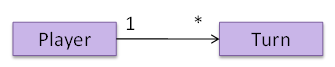
📦 A class diagram is a model that represents an OOP software design and is drawn using the UML modeling notation.
A model provides a simpler view of a complex entity because a model captures only a selected aspect. This omission of some aspects implies models are abstractions.
📦 A class diagram captures the class structure of the software design but not the runtime behavior.
Multiple models of the same entity may be needed to capture it fully.
📦 In addition to the class diagram, a number of sequence diagrams may need to be created to capture various interesting interaction scenarios the software undergoes.
How 
🏆 Can explain how models are used ![]()
In software development, models are useful in several ways:
a) To analyze a complex entity related to software development.
📦 Some examples of using models for analysis:
- Models of the problem domain (i.e. the environment in which the software is expected to solve a problem) can be built to aid the understanding of the problem to be solved.
- When planning a software solution, models can be created to figure out how the solution is to be built. An architecture diagram is such a model.
b) To communicate information among stakeholders. Models can be used as a visual aid in discussions and documentations.
📦 Some examples of using models to communicate:
- An architect can use an architecture diagram to explain the high-level design of the software to developers.
- A business analyst can use a use case diagram to explain to the customer the functionality of the system.
- A class diagram can be reverse-engineered from code so as to help explain the design of a component to a new developer.
c) As a blueprint for creating software. Models can be used as instructions for building software.
📦 Some examples of using models to as blueprints:
- A senior developer draws a class diagram to propose a design for an OOP software and passes it to a junior programmer to implement.
- A software tool allows users to draw UML models using its interface and the tool automatically generates the code based on the model.
Model-driven development (MDD), also called Model-driven engineering, is an approach to software development that strives to exploits models as blueprints. MDD uses models as primary engineering artifacts when developing software. That is, the system is first created in the form of models. After that, the models are converted to code using code-generation techniques (usually, automated or semi-automated, but can even involve manual translation from model to code). MDD requires the use of a very expressive modeling notation (graphical or otherwise), often specific to a given problem domain. It also requires sophisticated tools to generate code from models and maintain the link between models and the code. One advantage of MDD is that the same model can be used to create software for different platforms and different languages. MDD has a lot of promise, but it is still an emerging technology
Further reading:
- Martin Fowler's view on MDD - TLDR: he is sceptical
- 5 types of Model Driven Software Development - A more optimistic view, although an old article
Choose the correct statements about models.
- a. Models are abstractions.
- b. Models can be used for communication.
- c. Models can be used for analysis of a problem.
- d. Generating models from code is useless.
- e. Models can be used as blueprints for generating code.
(a) (b) (c) (e)
Explanation: Models generated from code can be used for understanding, analysing, and communicating about the code.
Explain how models (e.g. UML diagrams) can be used in a class project.
Can models be useful in evaluating the design quality of a software written by students?
UML Models 
🏆 Can identify UML models ![]()
The following diagram uses the class diagram notation to show the different types of UML diagrams.
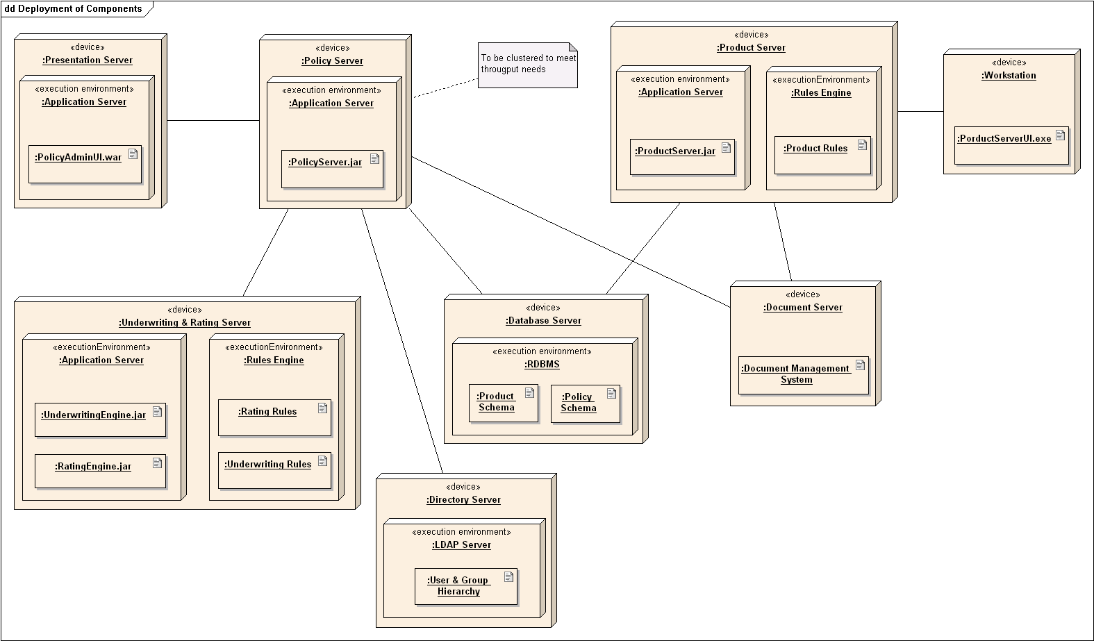
📦 An example deployment diagram:

source:https://en.wikipedia.org/
Modeling Structures
Class Diagrams 
🏆 Can use basic-level class diagrams ![]()
Class diagrams model the classes and how they are connected to each other.
📦 An example class diagram:
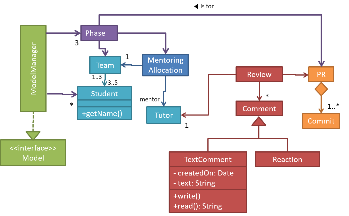
Which association notatations are shown in this diagram?

- a. association labels
- b. association roles
- c. association multiplicity
- d. class names
(a) (b) (c) (d)
Explanation: '1’ is a multiplicity, ‘mentored by’ is a label, and ‘mentor’ is a role.
Explain the associations, navigabilities, and multiplicities in the class diagram below:
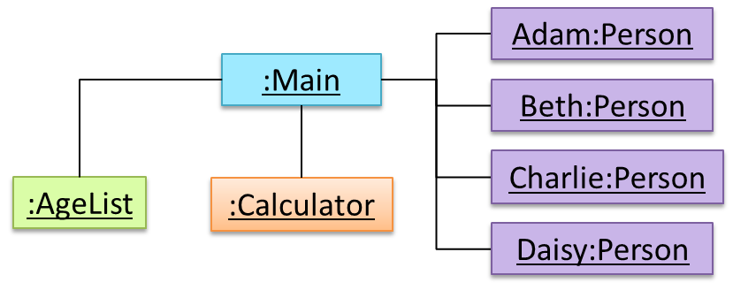
Object Diagrams
🏆 Can explain object diagrams ![]()
An object diagram shows an object structure at a given point of time.
Object Oriented Domain Models
🏆 Can explain object oriented domain models ![]()
The analysis process for identifying objects and object classes is recognized as one of the most difficult areas of object-oriented development. --Ian Sommerville, in the book Software Engineering
Class diagrams can also be used to model objects in the
📦 OO domain model of a snakes and ladders game is given below.
Description: Snakes and ladders game is played by two or more players using a board and a die. The board has 100 squares marked 1 to 100. Each player owns one piece. Players take turns to throw the die and advance their piece by the number of squares they earned from the die throw. The board has a number of snakes. If a player’s piece lands on a square with a snake head, the piece is automatically moved to the square containing the snake’s tail. Similarly, a piece can automatically move from a ladder foot to the ladder top. The player whose piece is the first to reach the 100th square wins.
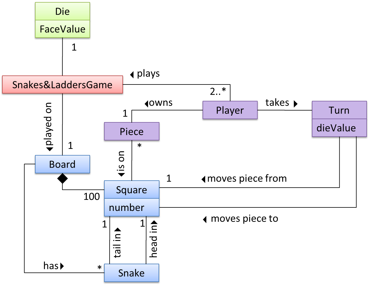
The above OO domain model omits the ladder class for simplicity. It can be included in a similar fashion to the Snake class.
OODMs do not contain solution-specific classes (i.e. classes that are used in the solution domain but do not exist in the problem domain). For example, a class called DatabaseConnection could appear in a class diagram but not usually in an OO domain model because DatabaseConnection is something related to a software solution but not an entity in the problem domain.
OODMs represents the class structure of the problem domain and not their behavior, just like class diagrams. To show behavior, use other diagrams such as sequence diagrams.
OODM notation is similar to class diagram notation but typically omit methods and navigability.
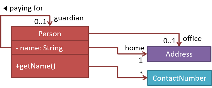
This diagram is,
- a. A class diagram.
- b. An object diagram.
- c. An OO domain model, also known as a conceptual class diagram.
- d. Can be either a class diagram or an OO domain model.
(a)
Explanation: The diagram shows navigability which is not shown in an OO domain model. Hence, it has to be a class diagram.
What is the main difference between a class diagram and and an OO domain model?
(a)
Explanation: Both are UML diagrams, and use the class diagram notation. While it is true that often a class diagram may have more classes and more details, the main difference is that the OO domain model describes the problem domain while the class diagram describes the solution.
Deployment Diagrams
🏆 Can explain deployment diagrams ![]()
A deployment diagram shows a system's physical layout, revealing which pieces of software run on which pieces of hardware.
📦 An example deployment diagram:
Component Diagrams
🏆 Can explain component diagrams ![]()
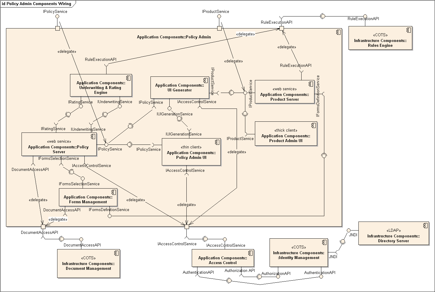
A component diagram is used to show how a system is divided into components and how they are connected to each other through interfaces.
📦 An example component diagram:
Package Diagrams
🏆 Can explain package diagrams ![]()
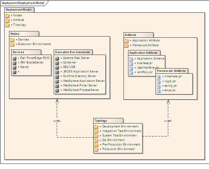
A package diagram shows packages and their dependencies. A package is a grouping construct for grouping UML elements (classes, use cases, etc.).
📦 Here is an example package diagram:
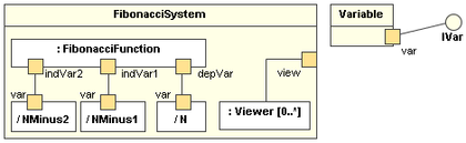
Composite Structure Diagrams
🏆 Can explain composite structure diagrams ![]()
A composite structure diagram hierarchically decomposes a class into its internal structure.
📦 Here is an example composite structure diagram:
Modeling Behaviors
Activity Diagrams
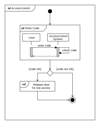
🏆 Can explain activity diagrams ![]()
Activity diagrams model workflows.
📦 An example activity diagram:

Sequence Diagrams - Basic
🏆 Can draw basic sequence diagrams ![]()
Sequence diagrams model interactions between entities for a given scenario.
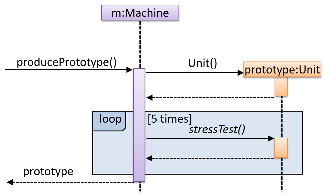
📦 Consider the code below.
class Machine {

    Unit producePrototype() {
        Unit prototype = new Unit();
        for (int i = 0; i < 5; i++) {
            prototype.stressTest();
        }
        return prototype;
    }
}

class Unit {

    public void stressTest() {

    }
}
Here is the sequence diagram to model the interactions for the method call prouducePrototype() on a Machine object.
Consider the code below:
class Person{
    Tag tag;
    String name;

    Person(String personName, String tagName){
        name = personName;
        tag = new Tag(tagName);
    }
}

class Tag{
    Tag(String value){
        //...
    }
}

class PersonList{
    void addPerson(Person p){
        //...
    }
}
Draw a sequence diagram to illustrate the object interactions that happen in the code snippet below:
PersonList personList = new PersonList();
while (hasRoom){
    Person p = new Person("Adam", "friend");
    personList.addPerson(p);
}
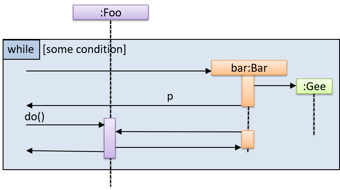
Find notation mistakes in the sequence diagram below:
Use Case Diagrams
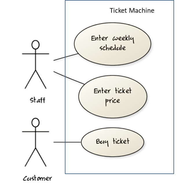
🏆 Can explain use case diagrams ![]()
Use case diagrams model the mapping between features of a system and its user roles.
📦 A simple use case diagram:
Timing Diagrams
🏆 Can explain timing diagrams ![]()
A timing diagram focus on timing constraints.
📦 Here is an example timing diagram:
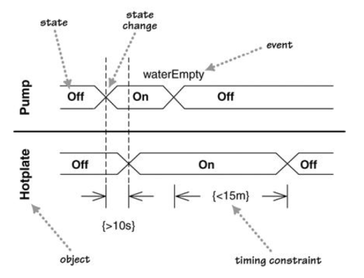
Adapted from: UML Distilled by Martin Fowler
Interaction Overview Diagrams
🏆 Can explain interaction overview diagrams ![]()
An Interaction overview diagrams is a combination of activity diagrams and sequence diagrams.
📦 An example:
Communication Diagrams
🏆 Can explain communication diagrams ![]()
A Communication diagrams are like sequence diagrams but emphasize the data links between the various participants in the interaction rather than the sequence of interactions.
📦 An example:
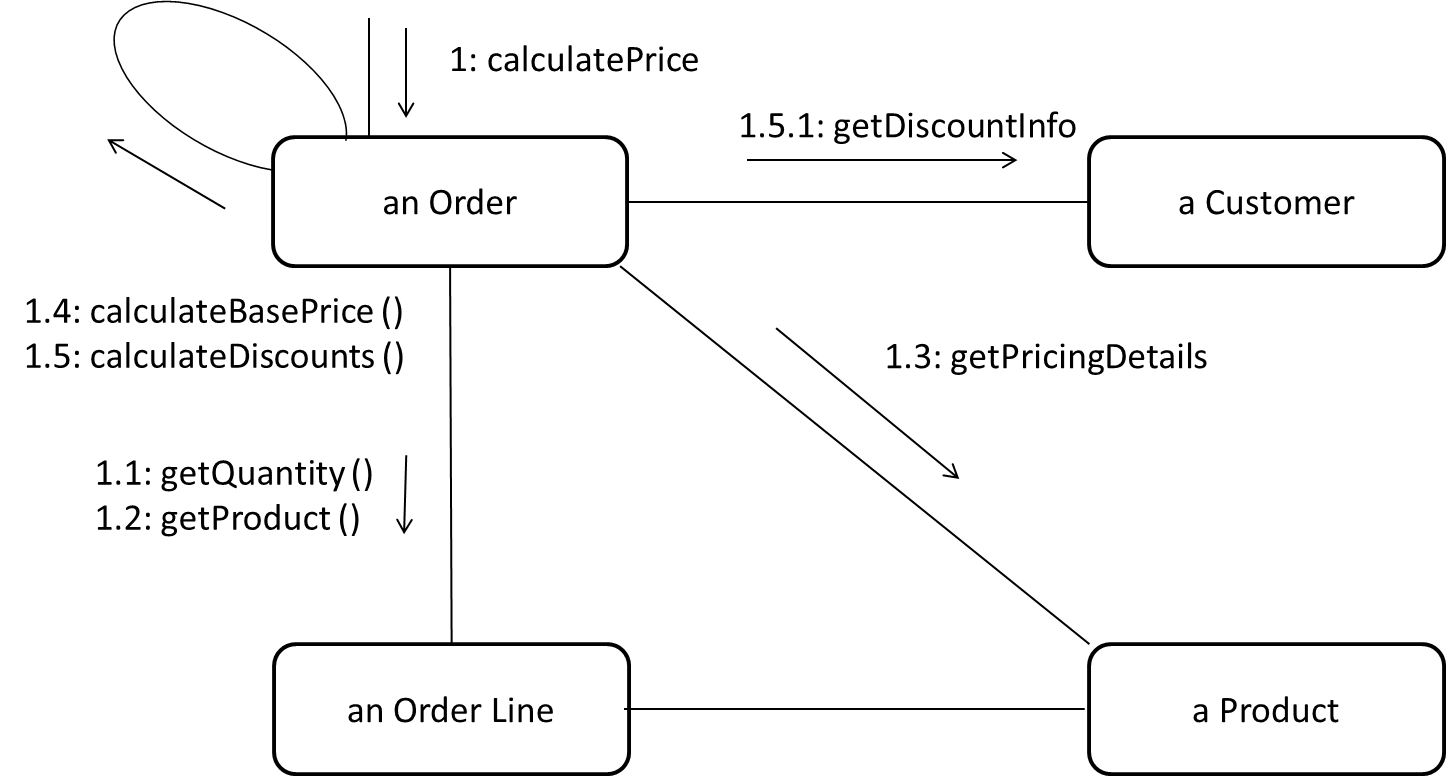
Adapted from: UML Distilled by Martin Fowler
State Machine Diagrams
🏆 Can explain state machine diagrams ![]()
A State Machine Diagram models state-dependent behavior.
📦 Consider how a CD player responds when the “eject CD” button is pushed:
- If the CD tray is already open, it does nothing.
- If the CD tray is already in the process of opening (opened half-way), it continues to open the CD tray.
- If the CD tray is closed and the CD is being played, it stops playing and opens the CD tray.
- If the CD tray is closed and CD is not being played, it simply opens the CD tray.
- If the CD tray is already in the process of closing (closed half-way), it waits until the CD tray is fully closed and opens it immediately afterwards.
What this means is that the CD player’s response to pushing the “eject CD” button depends on what it was doing at the time of the event. More generally, the CD player’s response to the event received depends on its internal state. Such a behavior is called a state-dependent behavior.
Often, state-dependent behavior displayed by an object in a system is simple enough that it needs no extra attention; such a behavior can be as simple as a conditional behavior like if x>y, then x=x-y. Occasionally,
objects may exhibit state-dependent behavior that is complex enough such that it needs to be captured into a separate model. Such state-dependent behavior can be modelled using UML state machine diagrams (SMD for short, sometimes
also called ‘state charts’, ‘state diagrams’ or ‘state machines’).
An SMD views the life-cycle of an object as consisting of a finite number of states where each state displays a unique behavior pattern. An SMD captures information such as the states an object can be in, during its lifetime, and how the object responds to various events while in each state and how the object transits from one state to another. In contrast to sequence diagrams that capture object behavior one scenario at a time, SMDs capture the object’s behavior over its full life cycle.
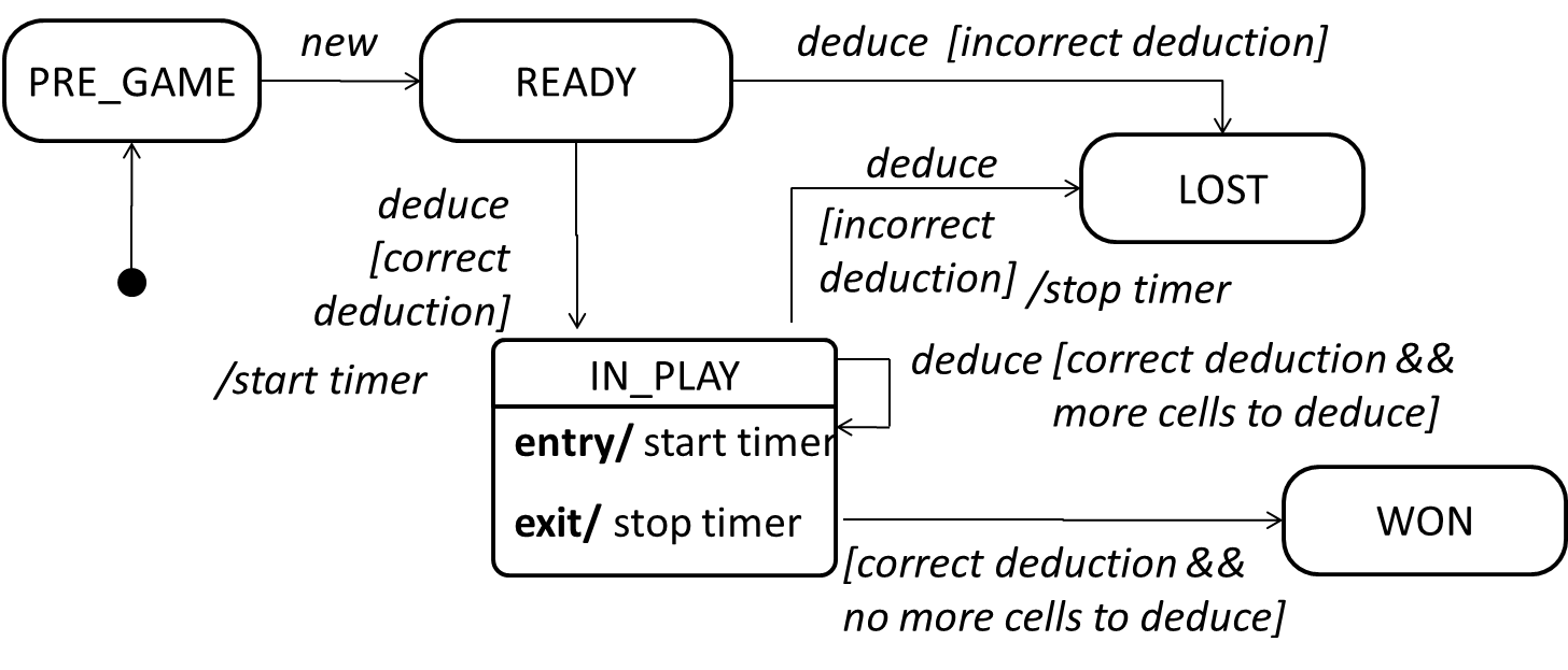
📦 An SMD for the Minesweeper game.
Review
Review
🏆 Can combine some modeling concepts ![]()
Explanation: A sequence diagram is a behavior diagram, not a structure diagram. An SD can represent how objects interact with each other (i.e., behavior), not how they are connected to each other (i.e. structure).